PRODUCT
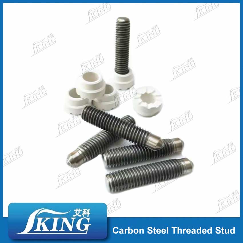

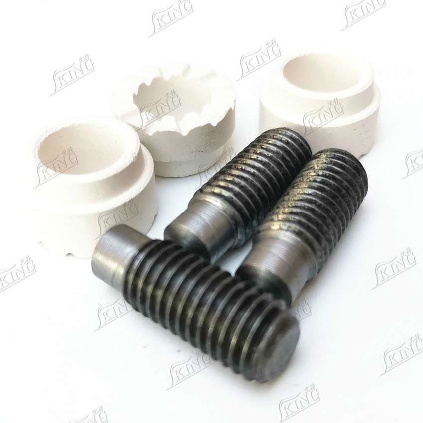
IKING Carbon Steel Threaded Welding Stud for Construction
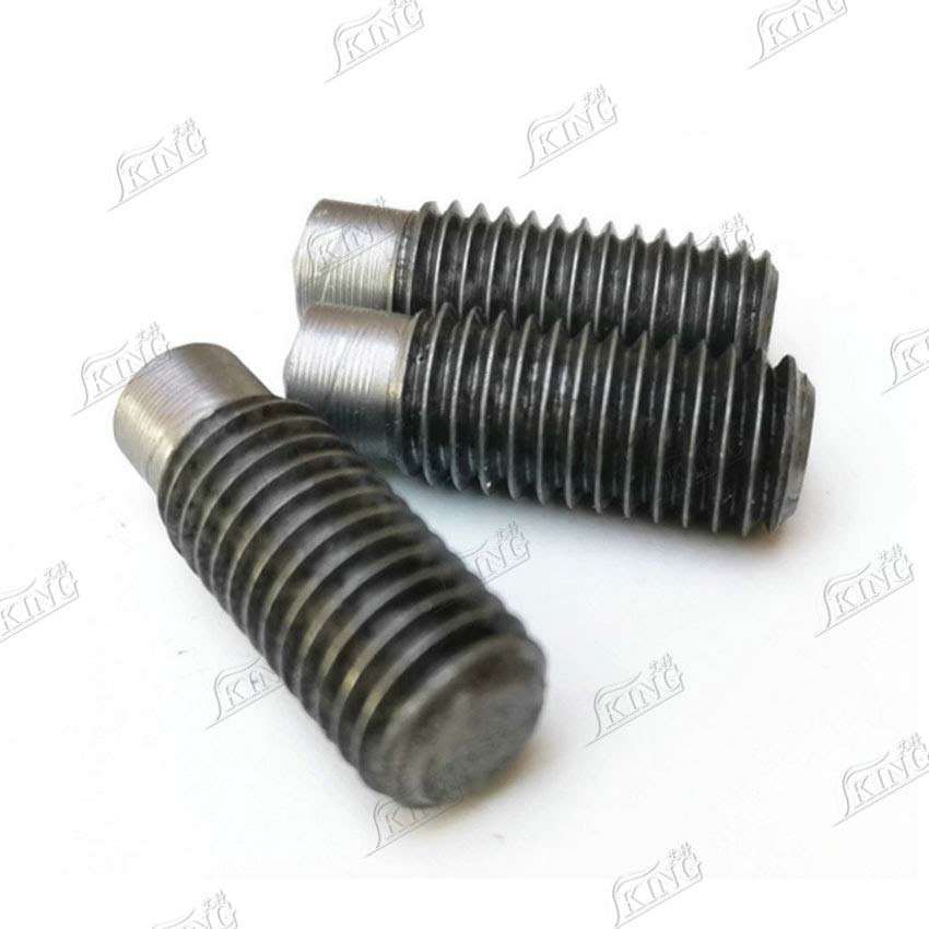
Our Carbon Steel Threaded Stud is designed for arc stud welding using arc welders or a welding machine, providing a fast, reliable, and high-strength threaded stud connection. Made from high-quality carbon steel, it delivers exceptional tensile strength with welds stronger than the stud itself.
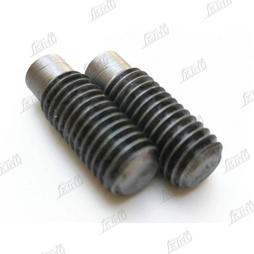
Material: Premium Carbon Steel
Surface Finish: Plain, copper plated, zinc plated, etc.
Performance: Minimal thermal deformation, ensuring stable welding on thin steel or sheet metal.
Product Introduction
The carbon steel threaded stud is a widely used fastening component in construction and industrial applications. It is designed for fast and reliable installation on metal surfaces, especially where strong connections are required.With stable performance and cost efficiency, this type of stud is suitable for large-scale projects and standard production environments.
 Product Advantages
1. Ultra-Stable Welding Strength
Made of premium carbon steel, this threaded stud forms a metallurgical-grade fusion layer when welded with arc welders or a welding machine, ensuring high tensile strength. The weld strength surpasses that of the stud itself, making it resistant to loosening even under vibration or impact conditions.
2. Minimally Pleasing Thermal Deformation
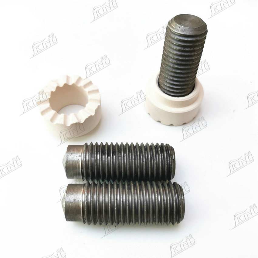
When paired with a welding machine, welding torch, and ceramic ring (optional), the process completes quickly—saving assembly time. Ideal for thinner profiled steel sheets or sheet metal parts, the carbon steel stud provides reliable performance with minimal thermal deformation.
3. Full-Scene Adaptability
Thread Specifications: Multiple thread sizes available (customizable).
Surface Treatment: Copper plating or zinc plating, meeting green environmental standards and suitable for humid or corrosive environments.
Welding Machine Compatibility: Fully compatible with arc welders and other welding machines used in stud welding applications.
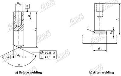
Product Parameters
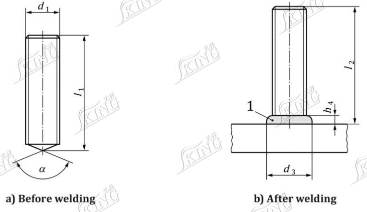
1. Fully-threaded stud (FD)
|
d1 |
M6 |
M8 |
M10 |
M12 |
M16 |
M20 |
|
d3ᵇ |
8.5 |
11 |
13 |
16 |
21 |
26 |
|
h4ᵇ |
4 |
4 |
4 |
5 |
7 |
7 |
|
α ± 7° |
140° |
|||||
|
l1 ± 1ᵃ |
l2 + 2.1 |
l2 + 2.2 |
l2 + 2.3 |
l2 + 2.8 |
l2 + 3.5 |
l2 + 3.8 |
|
l2 |
15–100 |
15–100 |
15–100 |
25–100 |
30–100 |
40–100 |
|
a Length l1 applies to angle 140°only(without tolerance). |
||||||
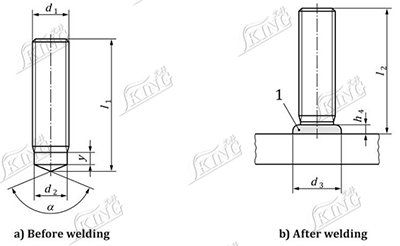
2. Virtually fully-threaded stud (MD)
|
d1 |
M6 |
M8 |
M10 |
M12 |
M16 |
|
d2 ± 0.1 |
5.35 |
7.19 |
9.03 |
10.86 |
14.6 |
|
d3ᵇ |
9 |
9.9 |
12.5 |
14.5 |
17.8 |
|
y |
5.5 |
6 |
6.5 |
7.5 |
11 |
|
h4ᵇ |
3.5 |
3 |
3.4 |
4.2 |
5.8 |
|
α ± 7° |
140° |
||||
|
l1 ± 1ᵃ |
l2 + 2.1 |
l2 + 2.2 |
l2 + 2.3 |
l2 + 2.8 |
l2 + 3.5 |
|
l2 |
15–100 |
15–100 |
15–100 |
20–100 |
25–100 |
|
a Length l1 applies to angle 140°only(without tolerance). |
|||||
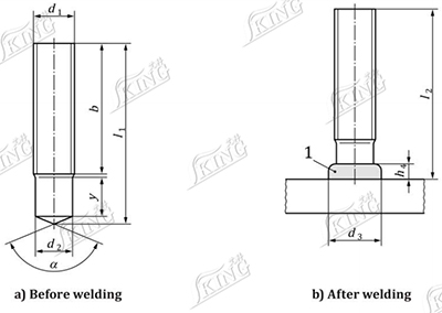
3. Partially threaded stud (PD)
|
d1 |
M6 |
M8 |
M10 |
M12 |
M16 |
M20 |
M24 |
|||||||
|
d2 ± 0.1 |
5.35 |
7.19 |
9.03 |
10.86 |
14.6 |
18.38 |
22.05 |
|||||||
|
d3ᵇ |
8.5 |
10 |
12.5 |
15.5 |
19.5 |
24.5 |
30 |
|||||||
|
h4ᵇ |
3.5 |
3.5 |
4 |
4.5 |
6 |
7 |
10 |
|||||||
|
α ± 7° |
140° |
|||||||||||||
|
l1 ± 1ᵃ |
l2 + 2.1 |
l2 + 2.2 |
l2 + 2.3 |
l2 + 2.8 |
l2 + 3.5 |
l2 + 3.8 |
l2 + 4.5 |
|||||||
|
l2 |
y+2P |
b |
y+2P |
b |
y+2P |
b |
y+2P |
b |
y+2P |
b |
y+2P |
b |
y+2P |
b |
|
15 |
9 |
- |
- |
- |
- |
- |
- |
- |
- |
- |
- |
- |
- |
- |
|
20 |
9 |
- |
9 |
- |
9.5 |
- |
- |
- |
- |
- |
- |
- |
- |
- |
|
25 |
9 |
- |
9 |
- |
9.5 |
- |
11.5 |
- |
- |
- |
- |
- |
- |
- |
|
30 |
9 |
- |
9 |
- |
9.5 |
- |
11.5 |
- |
13.5 |
- |
- |
- |
- |
- |
|
35 |
- |
20 |
9 |
- |
9.5 |
- |
11.5 |
- |
13.5 |
- |
15.5 |
- |
- |
- |
|
40 |
- |
20 |
9 |
- |
9.5 |
- |
11.5 |
- |
13.5 |
- |
15.5 |
- |
- |
- |
|
45 |
- |
20 |
9 |
- |
9.5 |
- |
11.5 |
- |
13.5 |
- |
15.5 |
- |
- |
- |
|
50 |
- |
20 |
- |
40 |
- |
40 |
- |
40 |
13.5 |
- |
- |
35 |
20 |
- |
|
55 |
- |
20 |
- |
40 |
- |
40 |
- |
40 |
- |
40 |
- |
40 |
- |
- |
|
60 |
- |
20 |
- |
40 |
- |
40 |
- |
40 |
- |
40 |
- |
40 |
- |
- |
|
65 |
- |
- |
- |
40 |
- |
40 |
- |
40 |
- |
40 |
- |
40 |
- |
- |
|
70 |
- |
- |
- |
40 |
- |
40 |
- |
40 |
- |
50 |
- |
50 |
- |
50 |
|
80 |
- |
- |
- |
40 |
- |
40 |
- |
40 |
- |
50 |
- |
50 |
- |
50 |
|
100 |
- |
- |
- |
40 |
- |
40 |
- |
40 |
- |
80 |
- |
70 |
- |
70 |
|
140 |
- |
- |
- |
40 |
- |
80 |
- |
80 |
- |
80 |
- |
70 |
- |
70 |
|
150 |
- |
- |
- |
40 |
- |
80 |
- |
80 |
- |
80 |
- |
70 |
- |
100 |
|
160 |
- |
- |
- |
- |
- |
80 |
- |
80 |
- |
80 |
- |
70 |
- |
100 |
|
a Length l1 applies to angle 140°only(without tolerance). |
||||||||||||||
4.Stud with internal thread (ID)
|
D6 |
M5 |
M6 |
M8 |
M8 |
M10 |
M10 |
M12 |
|
d₂ ±0,1 |
10 |
10 |
12 |
14.6 |
14.6 |
16 |
18.38 |
|
d₃ᵇ |
13 |
13 |
16 |
18.5 |
18.5 |
21 |
23 |
|
b+2P |
7.5 |
9 |
12 |
15 |
15 |
15 |
18 |
|
h₄ᵇ |
4 |
4 |
5 |
6 |
6 |
7 |
7 |
|
l₂ min |
15 |
15 |
20 |
25 |
25 |
25 |
30 |
|
α ±7° |
140° |
||||||
|
l₁ ±1ᵃ |
l₂ min + 2,3 |
l₂ min + 2,3 |
l₂ min + 2,8 |
l₂ min + 3,5 |
l₂ min + 3,5 |
l₂ min + 3,5 |
l₂ min + 3,7 |
|
a Length l1 applies to angle 140°only(without tolerance). |
|||||||
Welding process
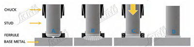
A. Stud is loaded into the weld tool and properly positioned against the base metal.
B. Trigger is depressed; Stud lifts, creating arc.
C. Arcing period completed, and the stud is plunged into the molten pool.
D. Weld is complete, the weld tool is withdrawn, and ferrule removed for inspection.
Application
1. Construction Engineering: Shear connection between steel structure beams, columns, and concrete (e.g., high-rise stiffened columns).
2. Manufacturing: Sheet metal fixing for automobiles, home appliances, chassis, and pipe support anchoring.
3. Equipment Assembly: Prefabrication of threaded connection points for electrical cabinets and lifting machinery components.
Engineering Design & Performance
The design of this product focuses on achieving a balance between strength and installation efficiency.
a.Optimized structure for consistent welding quality
b.Strong bonding performance with base materials
c.Reliable thread precision for assembly
d.Suitable for automated production environments
When used in arc stud welding, the stud forms a solid metallurgical bond, ensuring long-term stability in demanding applications.
|
Symbol |
Material/ material group/ property class |
Standard |
Mechanical properties of the finished stud |
|
FD |
4.8 |
IS0 898-1c |
See ISO 898-1 |
|
A2-50, A2-70,A4-50, |
ISO 3506-1c |
See ISO 3506-1 |
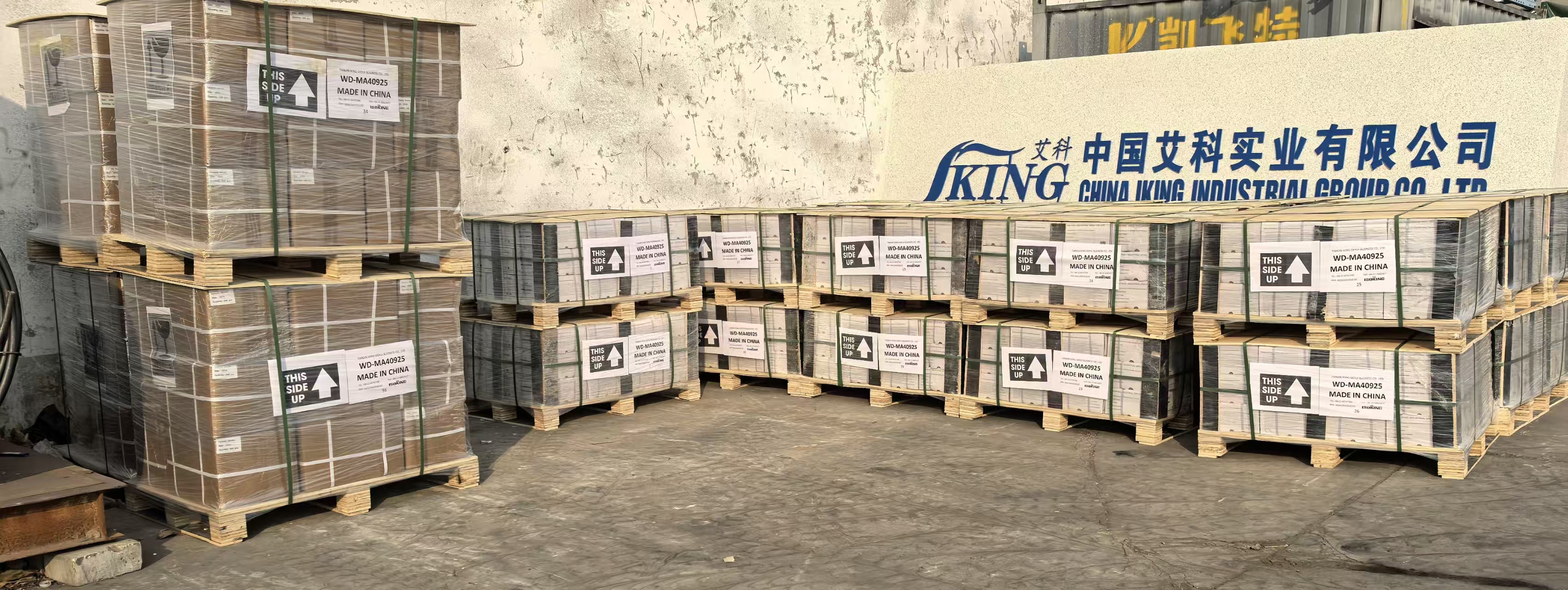
Why IKING
IKING provides reliable fastening solutions for industrial and construction applications. Our products are designed to meet practical project requirements, especially in steel structure installations.With stable quality and consistent supply, we support customers in achieving efficient and dependable results.
FAQ
1. What is a carbon steel threaded stud used for?
It is used for fastening metal components in construction and industrial applications.
2. What welding method is suitable for this product?
It is mainly used with arc stud welding for strong and reliable connections.
3. Can it be used in fabrication projects?
Yes, it is widely applied in industrial fabrication and metal assembly processes.
4. Is it compatible with standard equipment?
Yes, it works with most arc welding systems and tools.
5. What industries use this product?
It is commonly used in construction, manufacturing, and engineering.
6. Does it support structural applications?
Yes, it is suitable for use in steel structures and load-bearing systems.