PRODUCT
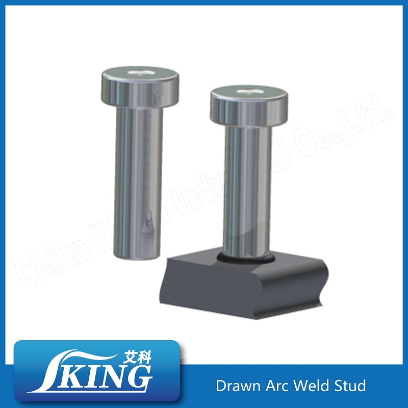
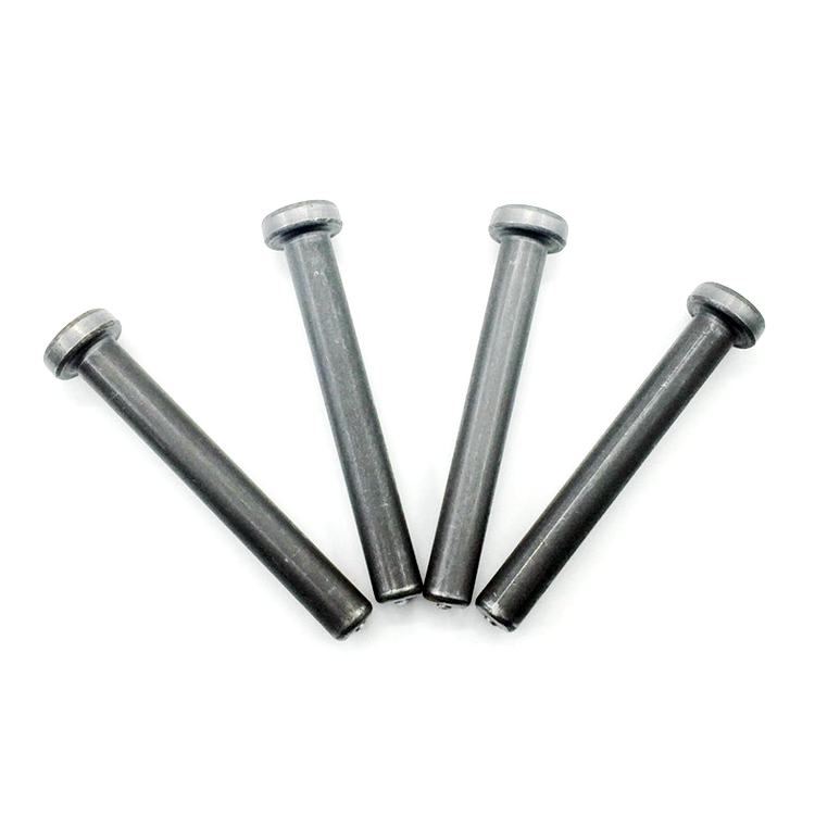
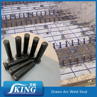
Shear Stud Connector
Shear Connector Specification
|
Product |
Shear Connector |
|
Brand |
IKING |
|
Material |
Low Carbon Steel – SWRCH15A/SWRCH18A |
|
Nominal Diameter (mm) |
Φ10, Φ13, Φ16, Φ19, Φ22, Φ25 |
|
Length Before Weld (mm) |
40 – 306 |
|
Surface Treatment |
Phosphating |
|
Flux |
Yes |
|
Yield Strength (0.2% offset) (MPa) Min. |
350 |
|
Tensile Strength (MPa) Min. |
450 |
|
Elongation (A5) % |
15 |
|
Origin |
China |

Features:
Made by high quality low carbon headed steel wire, make sure shear studs mechanical properties and welding property, no cracks on studs' heads.
High precision multi-station cold forming machine, ensure high precision and constant shear studs dimensions, round chamfer at the end of the studs.
High precision dimensions make the shear studs easy to load into the welding gun chuck and hold tight properly; Flat weld end with round chamfer make the shear studs easy to insert into the ceramic ferrule hole, and get 360 degree perfect weld collar.
Accurate calculated aluminium flux embedded by unique equipment automatically, ensure the welding quality and avoid cavities in the welding bead.
Surface Treatment:
IKING shear connectors used high quality low carbon steel proceed by pickling and phosphating, ensure the studs have long time anti-rust condition.
|
IKING Cheese Head Shear Connector With Ceramic Ferrule |
|
|
Material |
Low Carbon Steel |
|
Diameter |
Φ10, Φ13, Φ16, Φ19, Φ22, Φ25 |
|
Length |
40mm~500mm |
|
Surface Treatment |
Polished, anticorrosion, phosphating |
|
Bottom Treatment |
Slightly Curve or Chamfer |
|
Head marking |
IK or Client's headmark |
|
Quality assurance |
3 years |
|
Certifications |
CE, SGS, FPC BC1, UDEM, UKTC etc. |
|
Mechanical Properties of China IKING Shear Stud Connector |
|||
|
Hot sell Standard |
Tensile strength |
Yield strength |
Elongation |
|
EN ISO 13918 SD1 |
≥450 Mpa |
≥350 Mpa |
≥15% |
|
AWS D1.1 TYPE B |
≥450 Mpa |
≥350 Mpa |
≥15% |
|
BS 5400 |
≥495 Mpa |
≥385 Mpa |
≥18% |
|
AS/NZS 1554.2 |
≥410 Mpa |
≥345 Mpa |
≥12% |
|
JIS B1198 |
≥400 Mpa |
≥235 Mpa |
≥20% |
|
GB/T 10433 |
≥420 Mpa |
≥340 Mpa |
≥14% |
|
Shear Stud Connector Type SD (ISO13918:2008) Dimensions (mm) |
||||||
|
d1-0.4 |
10 |
13 |
16 |
19 |
22 |
25 |
|
d5±0.3 |
19 |
25 |
32 |
32 |
35 |
41 |
|
d3±0.3 |
13 |
17 |
21 |
23 |
29 |
31 |
|
h3±0.5 |
7 |
8 |
8 |
10 |
10 |
12 |
|
h4 |
2.5 |
3 |
4.5 |
6 |
6 |
7 |
|
l1±1.5 |
40~160 |
40~160 |
40~200 |
40~250 |
60~250 |
60~250 |
|
Burn off |
3 |
3 |
4 |
5 |
5 |
6 |
|
Ferrule |
UF10 |
UF13 |
UF16 |
UF19 |
UF22 |
UF25 |
Welding Process
Drawn arc stud welding for shear connectors can be done mechanically or automatically, using welding guns or welding heads. The shear stud is inserted into the stud holder and – fitted with a ceramic ferrule, if necessary – applied to the work piece. At the beginning of the welding process, the stud is lifted by the mechanism and, normally, first a pilot arc, then the main arc, are struck between the tip of the shear stud and the work piece. This causes the face of the stud and the parent material to melt. When the welding time has elapsed, the shear stud is plunged with little force (< 100 N) into the molten pool, and the current source is switched off. The ceramic ferrule is then removed. Figure shows the sequence of events using a ceramic ferrule.


